

When inspecting a used Heidelberg offset press, buyers usually focus on the printing units, feeder or ink control while treating the delivery section as an afterthought. In reality, the delivery cylinder, gripper bars, paper brake system and non-stop delivery configuration determine print pile quality, changeover efficiency and whether the machine can later be equipped with inspection, coding or downstream automation. Neglecting this area often leads to unexpected spending on chains, guides, brake rollers or servo motors after the machine has already arrived. Based on the delivery architecture common to CD102 and SM102 series machines, the following criteria can be checked on site before handover.
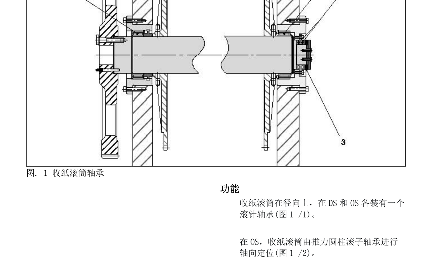
- Delivery cylinder bearings: radial needle bearings on DS and OS, with a thrust cylindrical roller bearing for axial location on the OS side; after service the spring assembly must return to 0.2–0.6 mm travel.
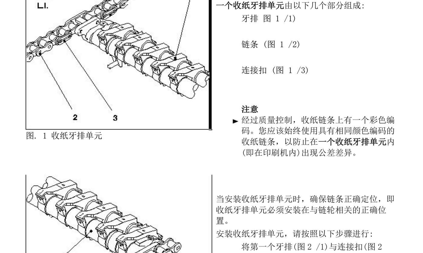
- Gripper bars and chains: both chains in a delivery gripper unit must carry the same color code; chain tension is maintained by 24 Belleville washers producing roughly 2,000 N pull, with about 2.5 mm spring travel.
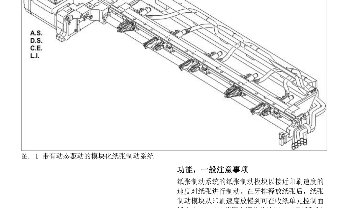
- Paper brake system: five brake modules slow the sheet from printing speed to a panel-adjustable 0–100% speed after the grippers release; single-sided and perfecting modules differ by the O-ring seal on the latter.
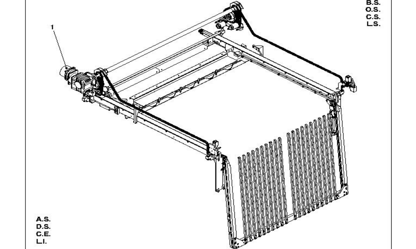
- Non-stop delivery: the auxiliary pile frame is driven up and down by motor 70M2 via a chain; support types are rake-style or pallet-style; lower-limit switch 70S1097 must stop the frame reliably.
- Pile control: ultrasonic sensor 12B65 handles fast/slow changeover, capacitive sensor 12B69 keeps the pile top at the sheet stop, and 12B132 times the catch fork entry during pile change.
1. Delivery Cylinder and Gripper Chains: Static Clearance and Dynamic Tension
The delivery cylinder transfers the sheet from the impression cylinder to the gripper bars, so its bearing condition determines long-term register stability. First check the OS thrust cylindrical roller bearing: the spring system must show 0.2–0.6 mm total travel. If the cylinder can be pushed axially by hand with noticeable play, the locating shims are worn or assembled incorrectly. Then listen and feel the radial needle bearings for noise, overheating traces or oil leaks.
The gripper chains are another high-wear area. Heidelberg color-codes the two chains in each delivery gripper unit so that matched pairs stay together. If the left and right chains show different colors, they have been mixed or replaced individually, which causes asynchronous grippers and uneven leading edges. Tension is produced by a spring pack of 24 Belleville washers providing roughly 2,000 N, with about 2.5 mm spring travel. When chains have stretched, the spring pack bottoms out and the gripper bars start to flutter even if the tension bolt is at its limit. The chain guide clearance should be 0.3–1.0 mm and uniform along the full length; local guide wear produces a periodic slapping sound.
2. Paper Brake System: Five Modules and Potentiometer Voltages
The paper brake system slows the sheet from printing speed to delivery speed once the grippers release it, preventing drift and smearing. The enhanced delivery uses a modular dynamic drive with five brake modules. A common brake motor drives the modules through friction wheels and a drive roller, while each module is timed individually.
Inspection can be done in three steps. First, run the press at low speed without paper and watch the five suction-belt modules: each should visibly slow down, stop and accelerate again, and the drive motor should be audible during dynamic acceleration. Second, check the potentiometer stop voltages: the DS stop should read 0.1–0.2 V and the OS stop 4.8–4.9 V; large deviations indicate worn module brackets or worn potentiometers. Third, inspect the drive roller bearings and the friction wheel covers: radial run-out on the drive roller or a flattened groove pattern on the cover will degrade braking consistency. Machines run mostly at low speed or with frequent stops wear the friction cover grooves faster.
3. Non-Stop Delivery: Rake vs. Pallet Supports
Non-stop delivery is valuable for long packaging or book jobs, but used machines often arrive with the frame but missing the auxiliary pile motor or support hardware. In the enhanced delivery, the auxiliary pile frame is moved up and down by motor 70M2 through a chain. Two support versions exist: rake-style for lighter stock and medium formats, and pallet-style for heavier board.
Key checks are limit and synchronization. When lower-limit switch 70S1097 is triggered, the frame must stop without chain slip. Lower the frame, support it on wooden blocks and hand-turn the press: there should be no abnormal resistance. If only the frame is present without rake or pallet supports, the feature is not production-ready; ask the seller for original part numbers and lead times. The pneumatic rear-edge limiter was optional from SM102 serial 537,478 and CD102 serial 537,456 onward, so verify the serial number if the seller claims this option on an earlier machine.
4. Pile Control and Joggers: Sensors, Servo Gains and Pneumatic Limits
Pile control determines stack quality and automatic pallet reliability. Ultrasonic sensor 12B65 monitors the pile top for fast/slow changeover; capacitive sensor 12B69 keeps the pile top at the sheet stop; and 12B132 times the catch fork entry during non-stop change. During inspection, interrupt each sensor by hand while the pile moves and confirm the corresponding signal appears on the control panel. No response means a failed sensor or aging cable.
The side joggers can be checked mechanically: the OS jogger plate should be 55 mm from the OS wall, and the inner distance between the two jogger plates should be 1,040 mm, corresponding to 704 ±2 incr on the service display. The front jogger and rear pile stop must be square to the pile support plate, with the suction-wheel stop 720 mm from the front jogger, corresponding to 556 ±3 incr. If the seller only says “the joggers are set” without showing the values, remeasure against these references. When the pneumatic rear-edge limiter is retracted it must be parallel to the press longitudinal axis with the indexing bolt disengaged and the position switch actuated; in working position it is perpendicular to the longitudinal axis with the indexing bolt engaged.
Common Misjudgments and Handover Tips
Mistake one: assuming a non-stop frame alone means non-stop delivery capability. Without motor 70M2, support rakes or pallets, and the lower-limit switch, the frame is only a shell. Mistake two: ignoring chain tension because the chains look quiet at low speed. Stretched chains may behave at low speed yet lose gripper accuracy at production speed. Mistake three: checking only whether the brake belts turn, without measuring potentiometer voltage and friction-cover wear, leading to inconsistent deceleration and smearing later.
Buyers should complete four checks before handover: hand-turn and listen to the delivery cylinder bearings; verify chain color codes, spring travel and guide clearance; run the press without paper and observe all five brake modules while recording potentiometer voltages; and confirm the completeness of non-stop hardware, motor and limit switches. If the seller cannot supply this data, make future rectification costs and responsibility limits part of the contract.
Conclusion: The delivery unit of a used Heidelberg offset press is not a peripheral attachment. It is a critical subsystem that affects print quality, changeover efficiency and future expansion. Including delivery cylinder bearing clearance, gripper-chain tension, the condition of the five brake modules and the completeness of the non-stop delivery package in the inspection checklist turns hidden retrofit costs into negotiable price space and lays the groundwork for later inspection, coding or robotic palletizing.