

On a used offset press, mechanical wear is visible and measurable, but the electrical system that truly determines long-term repair cost hides inside cabinets and cable ducts. For buyers and field engineers, a wiring diagram set that matches the machine's as-built serial state is the only reliable map for tracing circuits. Read it well and fault-finding turns from guessing into checking; if the drawings do not match the machine, even a young press can become a dead end. Using the 07/04 edition three-phase current flow diagram shared by the SM102 and CD102 formats as a sample, this article breaks diagram reading into four practical steps.

- Match the edition to the machine: the cover carries both an edition (Edition 07/04) and a document number (91.147.9331/01); one drawing set covers a specific production state, and cabinets may differ after later revisions.
- A complete drawing set has five parts: current flow diagram, equipment list, input/output list, location diagrams, plus safety instructions and code tables.
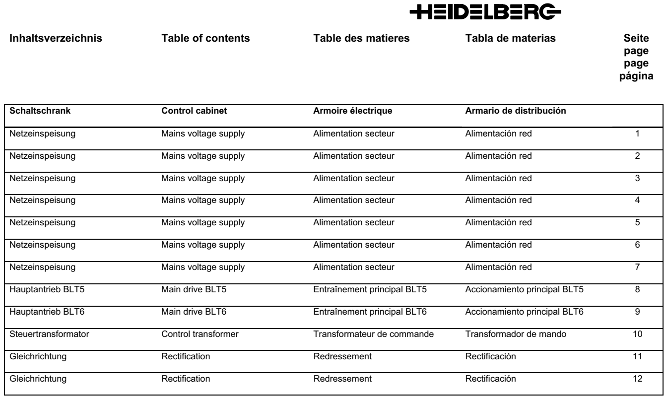
- Start from the cabinet page index: mains supply circuits occupy pages 1 to 7, the main drives follow, and contactor banks and power supply modules each have dedicated pages.
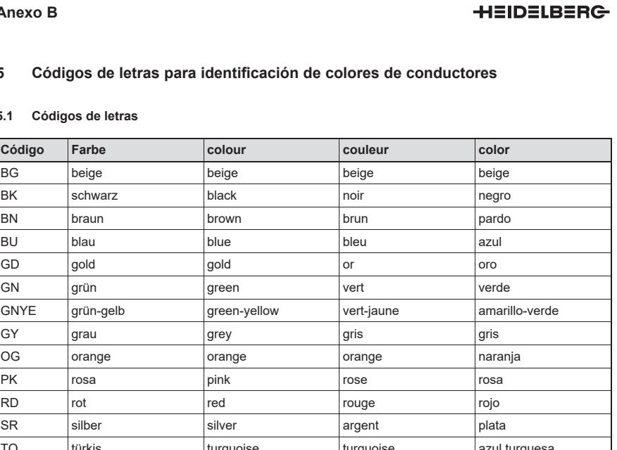
- Conductor colours use 17 standard letter codes such as BK black, BU blue and GNYE green-yellow; green-yellow is reserved for protective earth and must never be reused.
- Man Roland drawings are organised into zones 0 to 9: current flow diagrams, wiring schematics, switchgear layout, component placement, equipment list, instructions and terminal charts each occupy one zone.
- One hard acceptance rule for the safety chain: opening a guard while the press runs must stop it immediately and light the fault indicator on the console — both, or it fails.
Step one: the cover number is the drawing's identity card
Electrical configuration changes with production year and retrofit, so a disciplined drawing set locks its scope with an edition plus document number. For the medium-format flagships, SM102 and CD102 shared one current flow diagram set for the 2003-2004 period: edition 07/04, document 91.147.9331/01, and the preface states explicitly that the content reflects the series production state at the time of publication. When inspecting a used press, note the machine serial and the cabinet nameplate first, then compare them with the cover. If the seller's drawings differ from the machine's build year by several years, assume the diagrams may not match the hardware and verify every reworked line on site. The Roland system makes the point even more clearly: the 600 series drawings of 1985 correspond to Ser642, the 604 series drawings of 1987 to Ser645/653, and the 700 series splits into the 1999 Ser733 and the 2003 Ser742 generations — change the series number and the drawings change with it, the same logic as matching fault-code tables in Roland R700 fault code diagnostics.
Step two: the page index turns a cabinet into a book
A drawing set can run beyond a thousand pages, so disciplined sets include a cabinet page index that splits the electrical cabinet into functional chapters. In this 07/04 medium-format set, mains supply occupies pages 1 to 7, the two main drives BLT5 and BLT6 take pages 8 and 9, the control transformer page 10, and rectification pages 11 and 12; further on, the contactor bank spans pages 49 to 54, followed by power and interface modules such as VSM, BKM, SVM, OCIB, SEM and SAM, one page each up to page 60. The annexes are just as systematic: a CAN bus address table for peripheral units, assignments for the servo drive control board, an input/output list starting at page A1.19, and location diagrams from page A1.62. The standard field routine follows directly: look up the alarm or signal name in the I/O list to get signal and wire numbers, use the location diagram to find the device, then return to the referenced current flow or control page to measure voltage and continuity.
Step three: two small dictionaries — colour codes and abbreviations
Two tables in the annexes pay off daily. The first is the letter code table for conductor colours, seventeen entries: BG beige, BK black, BN brown, BU blue, GD gold, GN green, GNYE green-yellow, GY grey, OG orange, PK pink, RD red, SR silver, TQ turquoise, TR transparent, VT violet, WH white and YE yellow. When a drawing marks a wire BU or GNYE, you can predict the insulation colour before opening any duct, which halves the search area; and because green-yellow is reserved for protective earth, any earth conductor repurposed for control duty should be treated as a safety defect on the spot. The second dictionary is the abbreviation list that decodes equipment tags: SEK is a safety input board, SEM an interface input module, SNT a switched-mode power supply, SKIB a serial communication input/output board. Spare-part enquiries and equipment lists both depend on it.
Step four: the four-step tracing routine and safety acceptance
Chain the pieces together and the tracing routine becomes executable. Step one, start from the symptom or alarm and locate the signal name and wire number in the I/O list. Step two, predict the conductor colour from the letter code to narrow the physical search. Step three, find the device through the location diagram. Step four, return to the referenced circuit page and work segment by segment — continuity with power off, voltage with power on. The safety annex is just as actionable: personnel protection switches have their own table, and the key-switch replacement procedure even specifies a mounting radius of at least 45 mm plus a functional test — with the press running, opening the corresponding guard must stop the machine immediately and light the console fault lamp; if either fails, recheck the switch circuit. On a purchase inspection this two-minute test is the most direct health check of the safety chain.
Three misjudgements deserve a separate warning. Treating drawings as generic and assuming one set fits a whole series, only to find revised devices missing from the pages. Staring at power circuits while ignoring the I/O list, when a signal fault is solved by one page of the list rather than a day of page-flipping. Overlooking colour codes and letting a green-yellow earth conductor be reused as an ordinary control line, leaving the earthing scheme hollow. Note also that these drawing sets are published in German, English, French and Spanish with identical page numbering, so reading German is not a prerequisite for using them.
Conclusion: Wiring diagrams are the most underrated asset in used offset press inspection and repair. Match the cover number, navigate by the page index, find signals in the I/O list, read conductors by colour codes — after these four steps, most electrical problems turn from guessing into checking. Ask whether the drawings match the machine's generation before you buy, and run the guard-stop test on site; that is far easier than patching the gaps after the deal. Browse our used offset press listings for machines in stock.