

On a used offset press, print quality checks usually stop at printing a test form and eyeballing the crosshairs. What actually decides whether every sheet lands in the same position is the front-lay and side-lay registration system at the feed end, plus the electronically controlled positioning axes that drive it. Mechanical wear in this mechanism builds up gradually, while control-parameter drift arrives suddenly; combined, they produce misregister problems that look like neither a pure mechanical nor a pure electrical fault. This article breaks the system into three verifiable layers: maintenance intervals, detector self-test, and positioning-axis calibration.
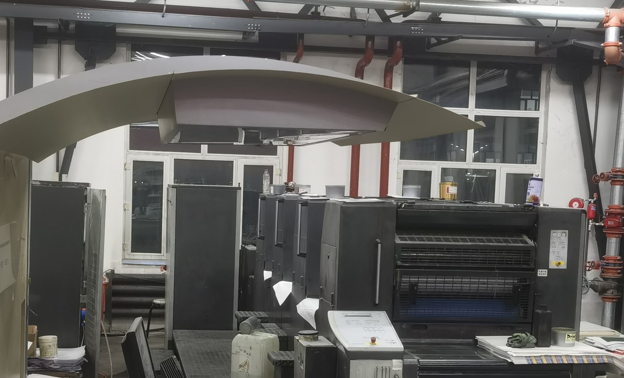
- The complete front-lay and side-lay assembly should be cleaned every 1,000 running hours, machine stopped and locked, with emphasis on paper dust and lint buildup.
- Six detector types — sheet pre-control, side control, leading-edge control, sheet-overshoot control, double-sheet control and missing-sheet control — need a clean brush pass every 50 running hours.
- Detector function can be self-tested by covering each one with a sheet of paper: the corresponding console symbol must switch from lit to dark; sluggish response indicates fouled optics.
- A typical electronically controlled side-lay offers a ±1.50 mm travel window, a tolerance of about 5 steps and a follow-up judgment window near 1,000 ms before a fault is raised.
- Positioning axes use two-stage limits: beyond threshold I no motion is allowed, inside threshold II travel is restricted to the working range.
- To cancel backlash, calibration axes approach an offset pilot point first, pause, then settle onto the target; failure to reach it lands the axis on the error list.
1. Two Overlooked Intervals: 1,000 Hours and 50 Hours
The first enemy of a registration system is not wear but lint. Clearances between the front lay, side-lay pull rail and detector brackets are in the millimeter range; dust bonded with oil mist forms a sticky layer that first blurs detector optics, then restricts rail travel. Mature maintenance schedules split the work into two cycles: the entire feeding-lay assembly cleaned every 1,000 running hours, the six detector groups every 50 hours. On a three-shift press that means detector cleaning is close to a weekly habit. When inspecting a used press, open the lay covers and look at the dust pattern — if detector windows are glazed over, the previous operator skipped periodic care, and the internals deserve equal suspicion.
2. The Paper-Cover Test: Judging the Detector Chain in Ten Minutes
Each of the six detectors guards one segment: pre-control watches sheet arrival timing, side control watches side-lay pull-in, leading-edge control watches the gripper edge at the front lays, overshoot control watches sheets overrunning the lays, double-sheet control guards overlapping feeds, and missing-sheet control prevents blank impressions. The functional check is simple: open the swing-gripper and transfer-cylinder guards, call up the detector status page on the first-unit console, cover each detector with ordinary paper, and confirm the symbol flips from lit to dark. Ten minutes covers the sensor, its wiring and the display path in one pass. A dead channel usually means a dirty window or a misaligned through-beam optic, not a failed sensor.
3. Electronic Side Lays: From Potentiometers to Ethernet Measurement
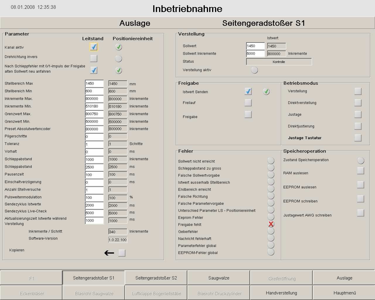
On newer presses the side lay is driven by a positioning axis, with travel and status shown directly on the console. A typical side-lay calibration screen lists a nominal ±1.50 mm range, a tolerance counted in steps (typically 5), and a follow-up distance paired with roughly 1,000 ms of pause time; any final-position error beyond tolerance is posted to an error list — target not reached, actual value outside the working range, wrong direction, mismatched parameters, or missing release signal. Newer Ethernet positioning units feed measurements from the drive-integrated encoder straight back to the console, eliminating the external potentiometer and its drift-related faults; the rotation-direction parameter must still match the mechanical mounting position, or calibrated values drift in reverse.
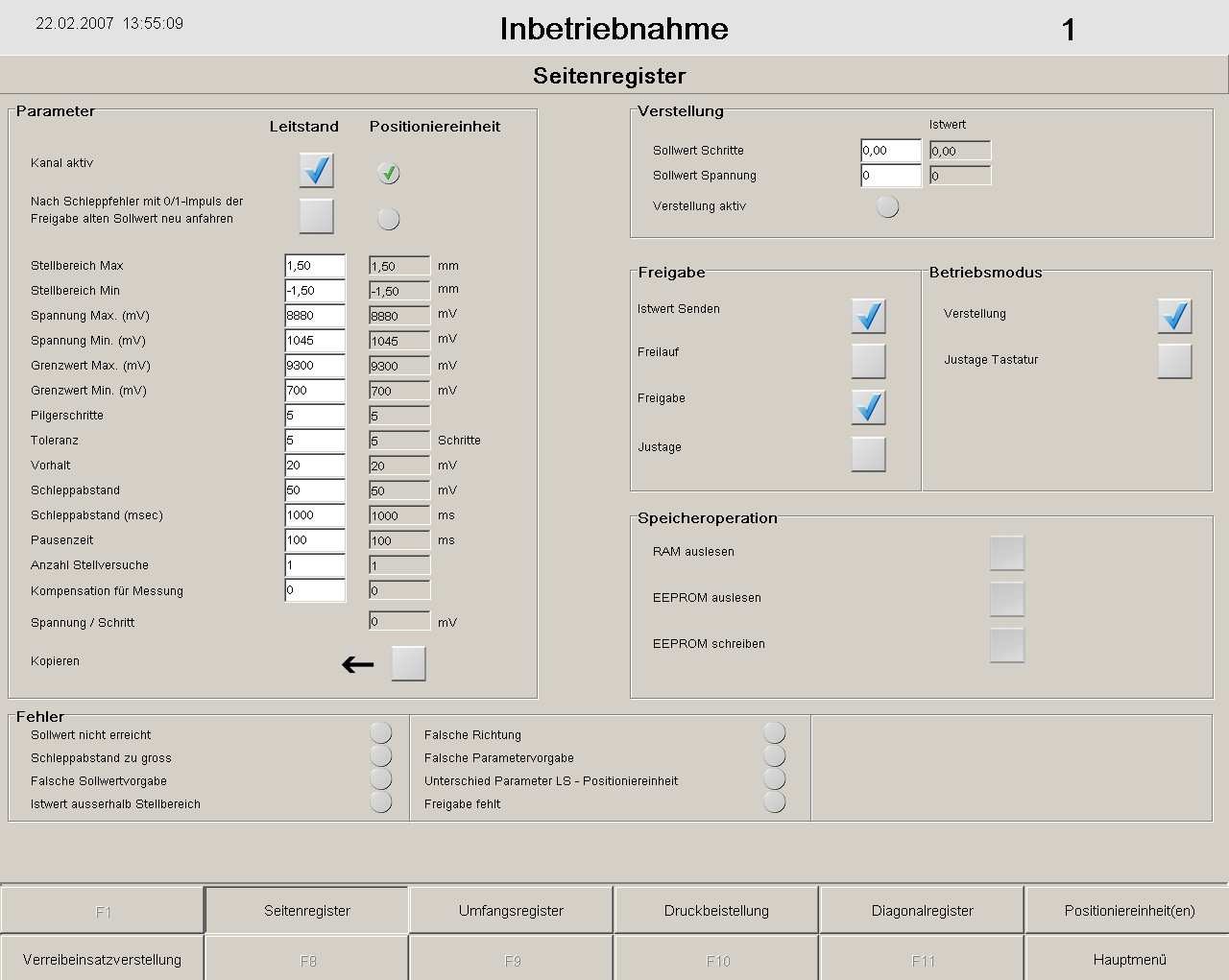
Two-stage thresholds define the protection logic: inside the working range, travel is free in both directions; past threshold II only an outward retreat is allowed; at threshold I motion stops entirely. Limit-switch parameters ahead of the mechanical stops decelerate the drive before it strikes hard stops, protecting the lay screw. Calibration itself is ratcheted: the axis first approaches a pilot point offset by a few steps, pauses, then settles on the final target so that drivetrain backlash is consumed at the pilot point. When an axis repeatedly reports target-not-reached, check mechanical play and screw lubrication before touching the current-limit parameter.
4. Used-Press Acceptance: Treat Registration as Its Own Subject
Fold the criteria into a four-step acceptance routine: first, look for cleaning evidence inside the lay covers; second, run the paper-cover test on all six detectors and record response speed; third, open the positioning-axis pages and check whether both side lays are symmetrically calibrated and whether the error list carries uncleared history; fourth, print a crosshair test form and sample register at the tail and both corners, separating mechanical error from control error. Side-lay direction jitter points to pull-roller and rail wear, while a constant offset suggests a drifted calibration zero — two diagnoses with very different repair bills.
5. Common Misjudgments and Shop-Floor Safety
The classic mistake is treating a missing-sheet false alarm as a double-sheet fault: the former watches trailing-edge arrival, the latter measures overlap thickness, and both trip when optics are dirty — clean first, diagnose second. Another frequent oversight is the parameter-mismatch warning: when console and positioning-unit values disagree, motion executes against one column only, which is why measured travel fails to match the screen. For safety, stop and lock the machine before entering the lay area; jog-only rotation with guards open; and never force a positioning axis by bridging its release signal — doing so defeats the entire limit-protection stack.
Bottom line: the front- and side-lay system stacks mechanics, detection and motion control into one subsystem. Four checkpoints — the 1,000-hour assembly clean, the 50-hour detector clean, the paper-cover test and the positioning-axis error list — will filter out most hidden problems at the inspection stage. Half of buying well is reading the printed sheet; the other half is verifying that this maintenance was actually done.


