

When a Roland R700 refuses to move a unit, loses ink-control response, fails format setup or reports a feeder positioning fault, the code should be treated as an entry point into the control chain rather than a simple part name. A service engineer must separate five questions: was the command issued, did the data cross the process bus, did the positioning controller complete initialization, did the actuator move, and did a protection circuit interrupt the result? Using 06006, 06101, 10102 through 10104, 06107 and 37034, this guide lays out a practical route for service work, used-press inspections and technician handover training.
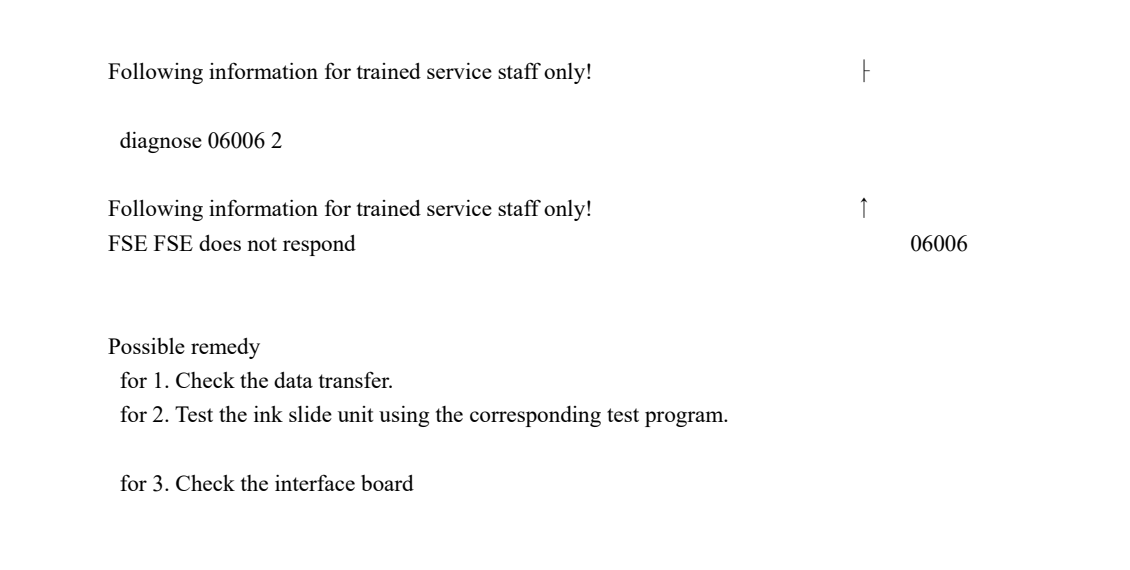
- 06006: Data transfer between the central console and ink-control unit is abnormal. Check the transfer path, ink-control unit and interface board.
- 06101: A positioning-controller node or subnode does not acknowledge initialization in time, leaving the press not ready. Do not blame the motor first.
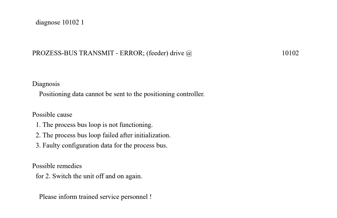
- 10102 to 10104: Process-bus transmission faults associated with feeder, delivery and color-console drives. Check the bus loop and configuration before replacing drives.
- 06107: The inking-unit setting did not complete correctly. Repeat the setting and zero adjustment before judging the controller.
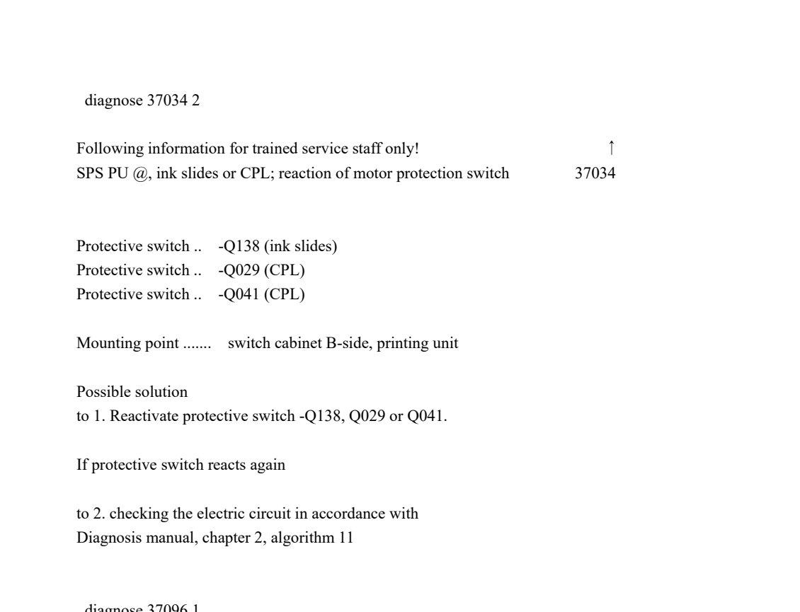
- 37034: An ink-slide or CPL motor protection switch has reacted. A repeat trip requires circuit, load and mechanical-resistance checks.
Put the code back into the control chain
Several alarms can appear on the same R700 at once. The first job is not to replace parts in the order shown on the screen, but to classify each code by layer. 06006 points toward data exchange between the central console, ink-control unit and interface board. 06101 points toward a positioning-controller node that did not complete initialization. 10102 to 10104 point toward process-bus transmission. 06107 connects the inking setting with zero adjustment. 37034 has already reached motor-protection feedback. This classification reduces the test area from the entire press to a communication segment, a control node or a defined actuator group.
06006 and 06101: communication is not the same as initialization
06006 normally appears when the ink-control command does not receive a correct response. Check data transfer between the central console and the ink-control unit, then check the related connection and interface board. If the alarm returns, use the applicable test function to determine whether the ink-control unit responds; a power cycle alone does not prove that the fault is repaired. The remedy path listed for 06006 maps cleanly to three layers: verify transfer, test the ink-control unit and inspect the interface board.
06101 is different. The POS-CTRL node or subnode does not answer, the positioning controller receives initialization data too late, initialization is aborted and the press remains not ready. Record the node and subnode identifiers, check the configured ID and version information, and confirm whether the process bus became temporarily unavailable after initialization. If a restart restores operation only briefly, the remaining fault may be in the node, bus loop, configuration or an additional-equipment data station. A temporary recovery is not a completed repair.
10102 to 10104: check the bus loop and configuration first
Code 10102 identifies a process-bus transmit error for the feeder drive. The central symptom is that positioning data cannot be sent to the positioning controller. The same reasoning applies to 10103 for the delivery drive and 10104 for the related color-console drive. Typical causes are a failed process-bus loop, a loop that failed after initialization, or incorrect process-bus configuration data. Use the sequence “alarm object, node response, bus loop, configuration data”. If several units fail together, suspect a shared loop, interface or configuration before suspecting several motors at the same time.
06107 and 37034: move from setting failure to protection feedback
Code 06107 means that the printing-unit inking setting was not completed correctly. Possible situations include a short disturbance during the setting procedure, power being removed during the procedure, an incorrect ink-slide zero adjustment or a defective positioning controller. Repeat the setting and complete the zero adjustment first. Only when the setting still fails should the investigation move into the controller, cables and actuator measurement. This separates a transient interruption from a persistent hardware fault.
Code 37034 names a more specific protection path: Q138 for the ink slides, or Q029 and Q041 for the CPL circuit, with the switches located in the B-side switch cabinet of the printing unit. After the first trip, confirm that the switch reacted under a safe maintenance condition and reset it only when the cause can be checked. If it trips again, do not keep forcing resets. Apply lockout and verify the mechanical resistance of the ink-slide or CPL mechanism, the transmission, wiring and circuit. Resetting is meaningful only after the reason for the protection action is understood.
A five-step sequence for service and used-press inspection
- Step one, record the complete event: Capture the code, unit number, requested action, timing, companion codes and whether it returns after a restart.
- Step two, identify the object: Separate the central console, ink-control unit, positioning controller, process-bus node, feeder or delivery drive and ink-slide/CPL actuator.
- Step three, separate shared-path from unit faults: When several units alarm together, check shared communication, interface and configuration; when one unit alarms, narrow the test to its node and load.
- Step four, test in order: Verify transfer and node acknowledgement before checking zero adjustment, mechanical resistance, protection switches and circuit continuity. Do not buy boards first.
- Step five, verify the trigger condition: Repeat the original action after repair and observe startup, initialization, format setting and continuous running to confirm that the alarm does not return under the same condition.
For a used-press inspection, stable ink-slide zero adjustment, feeder format positioning, delivery positioning and continuous running are more valuable than a single clean startup. Keep the code, unit location, test action, reproduction condition and remedy in the inspection record. If the press recovers only after repeated restarts, or a protection switch trips again under load, include that condition in the delivery risk and service budget.
Conclusion: R700 fault diagnosis is not about memorizing codes. Trace the chain from command, data transfer and node initialization to actuator motion and protection feedback. Codes 06006, 06101 and 10102 to 10104 locate the communication and bus boundary; 06107 connects setting with zero adjustment; 37034 directs the engineer into protection and load checks. Classify first, measure second and reset last. This is faster than replacing boards or motors blindly and gives a more reliable view of a used press electrical condition.


